I guess there's always a temptation to "make do and mend" when home-building a car, but usually the "mend" bit gets forgotten. One such area is the handbrake on the Brookvale Special. The Herald has the handbrake mounted centrally on the transmission tunnel, and it falls easily to hand as it should. Because the floorpan and steel transmission tunnel is removed in the build of the car, another location has to be found for the handbrake. In the case of my car, this was on the floor in the passenger footwell. To reach the handbrake involved stretching forward as far as possible - not ideal in busy road conditions. The handbrake had to move! And so developed one of those seemingly endless engineering jobs once a suitable location had been decided upon.
Anywhere in the passenger area was out, and the new transmission tunnel wouldn't be strong enough to support the handbrake. Besides, there would be no obvious access to the handbrake cables running to the rear wheels. How about outside the car? Well, not really as the opening driver's door would certainly get in the way. It had to be somewhere inside the car in the drivers area. I finally chose to locate it to the right of the driver adjacent to the panel in front of the door, and beneath the dash. All I had to do was to link the handbrake to the rear cable loop under the car - sounded easy.....
First I had to choose a suitable handbrake as the Herald one was clearly no good. The "new" handbrake had to be mounted in an upright position and the lower part be under the floor. After some research (Ebay) I found an MG Midget handbrake would appear do the job. I bid on the item I had found and won it for just a few pounds - a good start!
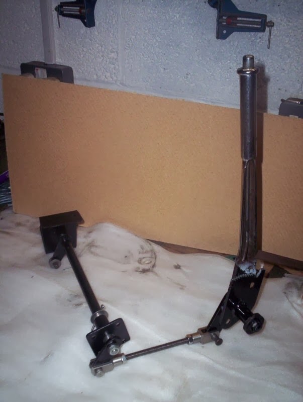
Now, the linkage - what would that look like? I would need a transverse shaft across the offside of the car, probably located to the rear to pick up the "Y" cable to the handbrake. This was currently routed to the nearside, but a quick reversal of its supporting metal strap and it was now pointing where I wanted it. Just the linkage to make then. Yes, well, sounds simple doesn't it? However, nothing was square to anything else and the transverse shaft would need to operate freely which necessitated a reasonably accurate shaft alignment. Oh well, crack on. The shaft was made and supporting brackets shaped and welded. I opted for using tube as bearings (well packed with grease) and had drop c ranks welded to either end. One end of the shaft was attached to the inner chassis rail, and the other end ran through the outer lateral outrigger. I used a length of threaded studding to link the cranks on the shaft to the crank on the bottom of the handbrake as this would give maximum adjustment options in the future.

The complete assembly on the bench
Once the assembly had been painted and fitted to the chassis rails I made up a plate to cover the hole in the floor, and used a piece of rubber to act as a "draught excluder". Would it work and hold the car? Well, the answer would appear to be "yes"!
The finished handbrake installation
Given the position of the mechanism I've made up a plate to deflect water from the bottom of the handbrake lever, and thoroughly greased all the movable parts.


